Vector Network Analyzer tutorial | VNA tutorial
This VNA tutorial covers VNA i.e. Vector Network Analyzer basics, VNA transmitter and receiver block diagrams, Vector Network Analyzer (VNA) measurements, VNA calibration etc. This tutorial also provides links to difference between scalar and vector network analyzers.
Network Analyzer :As we know network analyzer is used to measure impedance. At low frequency, we can simply divide voltage and current to obtain impedance. There are various equipments which performs this calculation such as volt meter, current meter, sine wave generator etc. This is not possible to do at high frequency. Hence here other technique is employed which measures incident wave, reflected wave and transmitted wave. Using these measurements different S-parameters are derived. At high frequency, ratio of reflected signal and incident signal gives us S11 or G.
As we know Network analyzers are of two types viz. SNA (Scalar Network Analyzer) and VNA (Vector Network Analyzer).
➨Scalar Network Analyzer (SNA) helps measure magnitude related measurements.
➨Vector Network Analyzer (VNA) helps measure both phase and magnitude related measurements.

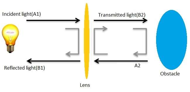
VNA的概念可以是最好的理解example of light rays incident on the lens device. The portion of the incident light is reflected by lens and some are transmitted through it. If there is no obstacle after lens the light will pass though smoothly. But if obstacle is there after lens, then part of light is reflected back(A2) towards lens and this gets splitted into two parts viz. one gets merged with original reflection(B1) and the other part gets merged with transmitted light(B2). This is shown in figure-1.
Hence,
➨Reflected wave before the lens = original beam reflected by lens + part of the reflection from the obstacle
➨transmitted wave = original beam transmitted through lens + partial reflected beam from obstacle

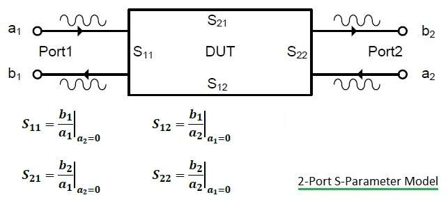
The light analogy described above can be applied to 2 port S-parameter model of RF device. The figure-2 depicts 2-port DUT with S-parameters and four wave types. As shown in the figure, waves leaving the device (i.e. b1, b2) are linear combination of waves which are input to the DUT (i.e. a1, a2).
Refer basics ofS-parameters.
VNA Transmitter Receiver Block Diagram

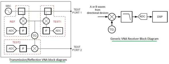
VNA usually measure incident and reflected waves though series of bridges or couplers. These are referred as signal separation devices in VNA. These are referred as directional devices. Imperfections in VNA measurements lies on coupling factor as well as directivity of directional devices. The figure depicts VNA block diagram depicting transmitter and receiver parts of vector network analyzer.
The other component is source which is the main stimulus used to characterize the response of the DUT. This source is tunable which tunes both frequency and power. The output can be confiured as single tone or multi-tone for different type of measurements. The source will sweep across the range of frequencies to collect the frequency response of the DUT. The source can also sweep across range of power values to obtain gain compression results of the DUT at fixed continuous wave frequency.
Figure-3 depicts VNA receiver part which measures phase and magnitude of travelling wave. This is done by converting analog form into digital form. The figure mentions single stage down converter which is used to convert RF to IF before processing incident and reflected waves.
There are two architectures of VNA (Vector Network Analyzer) viz. T/R set (Transmission/Reflection test set) and full S-parameter test set.
VNA measurements and VNA Calibration
VNA (Vector Network Analyzer) is used to measure S-parameters of active and passive microwave components.
Active components include transistors, amplifiers etc. While passive components include attenuators, cables, isolators, couplers, filters, circulators, bridges, antennas, transformers, duplexers, diplexers, triplexers, switches etc.
VNA is used to measure impedance, insertion loss, return loss and group delay.
VNA calibration is needed for accurate measurement of various parameters as well as to obtain results without any errors. For 2-port full S-parameter VNA, following calibration types are used:
• One path, 2 port calibration • frequency response calibration • full S-parameter calibration
This vector network analyzer tutorial is very useful for beginners to understand basics ofSNA and VNAand to understand difference between scalar and vector network analyzers.
RF Measurements RELATED LINKS
AM-AM conversion
AM-PM conversion
Error Vector Magnitude
RF Link Budget
Physical layer measurements
Design of RF frequency converter
C band RF Transceiver Design and Development
Production tests on RF and SoC devices
RF Terminology
what is RF
RF Power Amplifier
RF Mixer basics
rf synthesizer design
Noise figure vs Noise Temperature